

Basic MOSFET background and operation
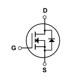
A MOSFET is basically a switch that can be controlled electronically - it's an acronym for Metal-Oxide-Semiconductor Field-Effect Transistor. Here is the electronic diagram of a MOSFET, note it has 3 leads labelled D, G, S:
Here is a schematic of the physical structure of a MOSFET:
 |
| From Wikipedia MOSFET entry image create by Brews_ohare |
These letters stand for:
- G: gate - (Metal) applying positive voltage to the gate with respect to the drain opens the switch. Note the insulation (Oxide, white) between the gate and the rest of the device
- S: source (Semiconductor) - positive voltage is applied here to induce current (between S & D)
- D: drain (Semiconductor) - ground or negative voltage is applied here to induce / receive current from the source
- B: body - the body of the device, bulk substrate
Note that even with the switch closed, although current can flow in both directions, it is preferential / easier for it to flow from S to D.
To put this all in practical terms, for the specific MOSFET I'm using, without applying any voltages the resistance across S-D is 2.8 M ohm (switch open). Applying ~3 V across the G-D causes the resistance (S-D) go down to 0.1 ohm (switch closed).
Using MOSFET's to control the boiler
In general our boiler (like many others) is controlled via two wires that are run through the house to where the thermostat is located to measure/control the temperature for that zone / area. The boiler applies 26 V AC across these two wires, and when current flows - for example by closing a switch connecting them - the boiler turns on. The boiler stays on as long as this circuit is closed, and turns off whenever it is open.
We can use a MOSFET to act as the switch, by connecting the wires to the Source and Drain, however there is a problem: the MOSFET will preferentially allow current to flow when the voltage at the source is higher than the drain (i.e. lower resistance measured S-D). Since the boiler is using an AC voltage, the MOSFET will allow almost unimpeded current for half the cycle of the AC voltage - the other half will be attenuated.
 |
| link to google drawing |
The sources of both MOSFETs are connected to each other and the ground (GND) of the electric imp, the electric imp control voltage (Pin 1) is connected to both gates, and the boiler wires carrying 26 V AC are connected to the drains of the MOSFETS. The electric imp breakout board also has a temperature sensor, and the electric imp is programmed (link to code) such that when the temperature measured drops below the set point, it applies voltage to Pin 1, causing the MOSFET gates to be biased and closing their switches, allowing the boiler control current to blow, turning on the boiler. After 20 minutes, the electric imp checks the temperature again, if it is above the set point it turns off the voltage to pin 1, causing the MOSFET gates to be unbiased, opening the switches and blocking the boiler control voltage from flowing.
Here is a diagram I found illustrating how the current flows through the two back-to-back MOSFETs:
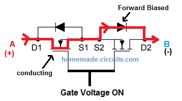 |
| from https://www.homemade-circuits.com/bidirectional-switch/ "Basic Functioning Details" |
To more fully understand this, I used a circuit simulation tool (PartSim - free! Awesome to explore ideas!) to test some very simple MOSFET circuits. Here's an example circuit I used:

Running the simulation on this circuit yields a plot of the current (measured at M3) vs. sweep voltage:

For the circuit with two MOSFETs wired "back-to-back", for the positive applied voltage one will be operating in the higher resistance mode, the other in lower resistance mode - and the same is true for negative applied voltage. Hence there will be symmetric response to positive and negative voltage.
Random: PartSim let's you share the project in an iFrame, which let's you embed it in a web page allowing you to zoom/pan to look at the circuit:
Doesn't really matter for this simple circuit, but kind of a cool feature.
References:
Low-Cost AC Solid-State Relay With MOSFETs (Rev. A) - section 2.1
https://www.homemade-circuits.com/bidirectional-switch/ - "Basic Functioning Details"
No comments:
Post a Comment